


Story
(Hardware)
Designer
Final Spec
Concepts
Old Comp
Software
People
Media
Support
Future
Links-
The ICT 1301 Resurrection Project.
The Designer, Dr Bird.
*** Designer Visit Day ***
*** Fifty years after he designed the machine ***
the designer meets the last working ICT 1301 Computer in the
World.
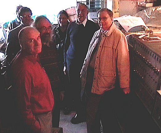
On the 13th Oct 2004 The designer of the ICT 1301, Dr Bird, visited the project with
Hamish Carmichael of the BCS. Dr Bird formulated the design 50 years before, and now in his
81st year, we were proud to show him the last remaining ( and Running ) ICT 1301 in the
United kingdom.
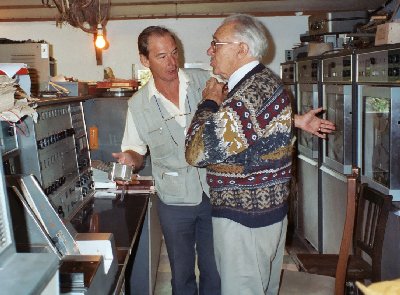
The following Photo was donated by John Prockter, the other stills were extracted from video footage of the day, so my appologies for the low quality, I will post up more of John's information as space and time allows.
Preparation for the video shoot, we just could not let this chance go by
Dr Bird gave a short introduction to the design of the system, for a small
video we are planning of the project !
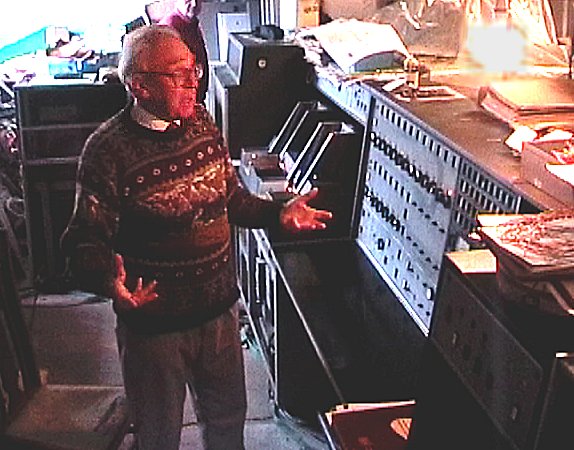
The background to the history of the design was facinating, and at Eighty One
years of age, his continued enthusiasm for the design is outstanding.
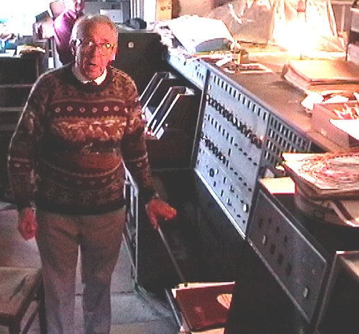
I will attempt to add a transcript of his dialog here soon, which
encompassed the CDL days of the design, and its inception.
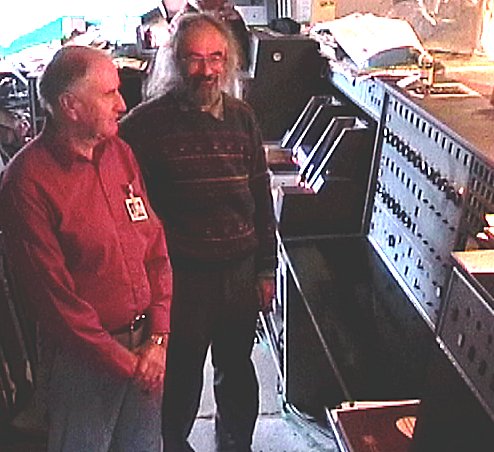
The first enginner to look after the Computer in London University was
John Prockter, who drove a long way to be with us on the day. He is standing to the left of
the picture, and next to Stuart Fyfe, one of Flossies earlier owner's when the machine was
taken out of London University. John's choice to wear his original Company staff pass, for the day showed the kind of commitment people put into thier working life, and the machines they worked on. " Nice one John "
Engineers who worked on this type of machine were most welcome
So it was hello from John Chambers, Brian Ferres and Ron Harding, ( aka Kots !)
as he is the West kent retired engineers group, Keeper Of The Scrolls.
We were also joined after lunch by Tervor Chapman, who
worked on these machines in the Stevenage Factory !
GEC The Design partners
The machine is British through and through, it was a joint project
between GEC Telephones of Coventry and International Computers and
Tabulators, which was an amalgamation of the British Tabulating
Machine company and Power Samas, the two British tabulating machine
companies. BTM had been the holders of the rights to all Hollerith/
IBM technology throughout the British empire. They decided to give up
these rights and build the 1301 in competition with IBM. In
retrospect, probably not a good move! Probably the biggest selling
point of the 1301 was that it could perform British currency
calculations in hardware. It is probably the only range of computers
to be able to add and subtract pounds shillings and pence, and to be
able to multiply sterling amounts by decimal numbers. Even the
components are British made except for some in the tape sub system as
the tape decks were American made Ampex TM4 units.
It is a serial/parallel machine, four bits in parallel to form a single decimal or sterling digit by 12 digits serial to form a complete word. The decimal point and the corresponding sterling position were held in registers. It was the first ICT computer to use transistors and core memory (quaintly called the Immediate Access Store (IAS)). This was arranged as 48 bits plus two parity bits by up to 2000 words. A machine could be fitted with a maximum 2000 words. This is NOT 2048 words, a 1301 is not a binary machine. It uses binary coded decimal for its instruction set. Though a digit can be made to hold values of 10 to 15, these are not valid in instructions, and are not decoded as addresses. There is no program counter, though if there was one it would be BCD as well. Even machine code programmers can think in decimal almost all the time.
GEC's expertise in large scale manufacturing, of complex systems was in Telephone exchances, therefore several design concepts common to exchanges surfaced in the design
For reliability its designers avoided plugs, sockets and edge connectors except in some of the peripherals. Permanent connections are of course soldered, but where maintenance requires the possibility of replacing a printed circuit board, it uses a technique which I think is unique. The PCB carrier has up to 25 pins, each one half of a square, at the FRONT where they are accessible. Each PCB has up to 25 matching pins which together with the ones on the carrier, form a square. This square is wrapped with a helix of bare tinned copper wire, and I have been told this forms a weld on the corners, though personally I think the pin just presses into the tin very hard and is held there so it cannot fail to conduct electricity. Anyway the effect is not in doubt, these connections do not fail unlike gold plated edge connectors. If the machine had used conventional gold connectors on its 4000 odd PCBs I doubt if it would have ever worked when new, and certainly not 44 years on. Another benefit of the design is that the PCBs can be mounted back to back in a rack and still have access to every single terminal.
A positive benefit of the front wire wrap is that any individual pin can be unwrapped and a sliver of plastic (made for the job) can be slid in to isolate that one signal. This is extremely useful when fault finding the hardware as it uses diode transistor logic and hence the wire 'OR'. Trying to find which of many input signals if pulling a signal down to a 1 ( MINUS 6.3 volts ) would be very difficult without this facility. The same thing applies when a faulty PCB is pulling a signal high or low, is it the signal source driving the signal incorrectly or is it the destination gate pullling it up or down, or is it a fault in the wiring in between, caused by a faulty wire wrap, a blob of solder, a piece of wire or a screw which has fallen and lodged where it should not or even a bent pin or the body of an insect, though I have never encountered a real bug yet.
Making it Work
We were delighted to hear some stories about this machine during its design phase
this included the problem of trying to get the layer of magnetic oxide on the surface
of the drum, just right. Too thick and it could not be saturated by the read write head
current, too thin and it did not retain a big enough signal to be recovered anyway. After many idea's the designer was called to the Drum production unit and told that they may have found the answer. Checking the sample drum he was delighted to see a perfect surface thickness, all down the length and width of the drum. "How did you do that" was the obvious question, and the answer was.
After coating the drum, the operator moistened his finger and ran it Potters Wheel style along the length on the drum as it slowly spun. The result was a reliable source of the major component of the drum store.
I will confirm the quality of the final surface, as an engineer I replaced a drum on a machine that had run a job with a high security classification. We were allowed the old Drum back only after we had removed the Oxide coating from the outgoing Drum. At the end of the exercise we presented the client with a box of cloth soaked in Toluene ( the solvent ) and heavy with the stains of the dark brown oxide. " Here is your Data " was our comment, " Prove It " was the response, so we showned the client the Aluminium drum which was cleared of all oxide and just showed the yellow surface primer. Then and only then were we given a document saying we could remove the now useless drum from the building.
