


Story
Hardware
Software
People
(Media)
Images
Sounds
Animation
Gallery
Support
Future
Links-
The ICT 1301 Resurrection Project.
Images and Facts from the Project.
The Machine and its location
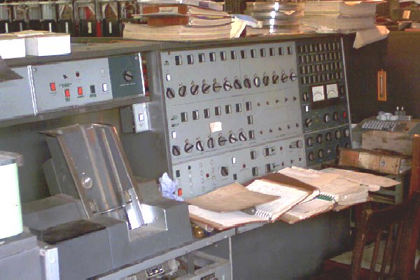
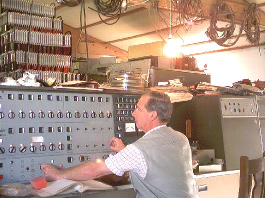
The state of repair is slowly improving, assisted in most part
by a comprehensive set of manuals and original documentation.
And not overlooking the spare boards you can see piled on the
top the the machine.
The major Repairs
Major components have failed over time, the worst experiece we have had is with Neoprene which crumbles topowder and some hard rubber components which suffer from surface splitting and then loss of integrity.
The Second set of feed rolls in the card reader had an upper rubber set running against a lower steel set,
The uppers had failed so new tyres were made, but this time from White Nylon two inch bar stock and then
force fitted and turned up between centers in a lathe. They have worked well and are one of the success stories
we have had.
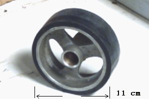
The Stacker drum on the Card reader was an 11 cm diameter inch Neoprene Drum, 3 cm wide and transports the current
card from just after the Read and Reject Station to an upwards stacker mechanism, this one was a real challenge.
After the surface of the drum was cleaned up the we calculated that we needed about 0.75 cm of covering to bring the drum
up to full diameter, and as the diameter controlls the speed that the card is delivered into the stacking mechanism
it was vital that we got this right. We had no option for a new spare so what could we use ? One option was to mould
the surface with an amalgumating Rubber compound which is available in both soft or hard forms, but we knew we than had
to turn the surface down to the right size ( of ever cylindricaly grind the surface )
However we settled on using over seven layers of Car tyre inner tube, each layer opened up and passed over the drum
like a big elastic band, then allowed to spring closed onto the glue covered layer below. The major advantage was that
at speed this drum causes it diameter to expand due to centrifugal force, and each layer was trying to stay in place
and just plain ' hang on ' to its lower layer. Just to complicate it a bit more there are guide rollers which push into
the surface, so in the stopped state it could have caused an impression to be formed in the drum. The idea has worked,
well lets be honest and say ' Mostly ' . We had to sacrifice the top layer as we had over done the number of layers,
and some horizontal settling has given us problems with this solution. We actually get crumbs of rubber settling into
the mechanism, not good ! .
The drum was not an easy task to install and it's removal will be a challenge should we come up with a better idea !
it has been mostly succsessful, but not one of our best fixes to date.
Scratch Built Solutions
It is not possible to obtain components for the machine after fourty five years, and in some cases substitute parts are usedWe try to recycle all parts back into the machine, after repairs. But from time to time we have a need to construct new
interfaces from scratch. Now a few bistables and some gates in Flossie logic is a whole rack full, so we use what we are
comfortable with, mostly TTL logic. The items listed below are the interfaces we have used over the years and although we
could have chosed modern micro-controllers, it is easier to move a wire from pin to pin on a PCB than it is to
reprogram a micro-controller chip when changes are required.
Our biggest problem then becomes where to source early versions of TTL that are over thirty years old,
that have been stored properly, and not been allowed to develop corrosion on pins and have been treated with
due electrostaic care.
All of the above to fix up a computer that is over fourty five years old, ( see what I mean about a problem ? )
Now I very rarely recommend Commercial suppliers, however over the years suppliers who have given exceptional service.
Should be mentioned so here goes:-
The Computer Junk Shop
Trades on Ebay and has delivered such a quality of service and components, that it is allways my first port of call.
Dont be fooled by the name, I have Never recieved ' Junk ' from this supplier only ever quality parts in sufficient
quanities to fullfill our needs, which sometimes can mean quantities of over 150.
I also use this supplier for parts I use at SHEDLANDROBOTICS but that is another Story ( and another Web Site )
Interface Mk3
Version one = This version was tried late in 2006. It had to be replaced as the TTL inputs were bieng blown up
due to the negative swing on the inputs. TTL does not tolerate that kind of treatment.
Version two = This version had clipping transistors and current limiting resistors between the 1301 outputs and
the inputs to the logic. Better isolation has meant that we do not blow up TTL at all but we do blow up transistors
from time to time. The comlexity of the 1301 to FIFO interface means we have had to do a lot of decoding and
we have just run out of room on this board, to allow us to re-design on the fly in a live situation.
Enter the next version for 2008.
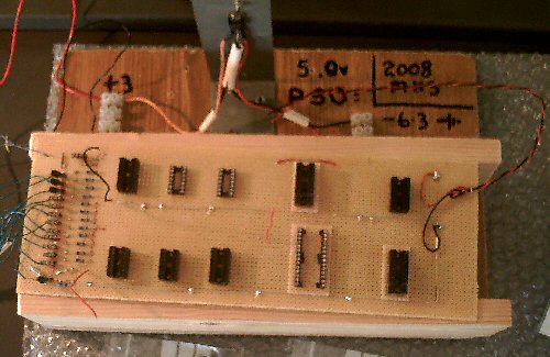
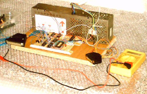
Version three = This version will be trialed in late 2008. It has a large and open design to do on the fly
development and if we can get the 1301 to FIFO section working then the rest should drop into place quite swiftly.
It also has taken out the Switch mode PSU which was giving a lot of the isolation problems we were suffering !
And after our experiences above even the clipping transistors are plugable for rapid deplacement. We have also
gone for a wrapped wire prototype design which means we can make changes quickly ( well we hope so anyway )
Here is a simple overview of what the design is supposed to do when we get it working !
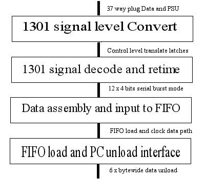
To date this design has taken about 4 years to develop and should offer a way to unload the tape data base.
However to date the data transfered is a factal 0k.
Interface Mk2
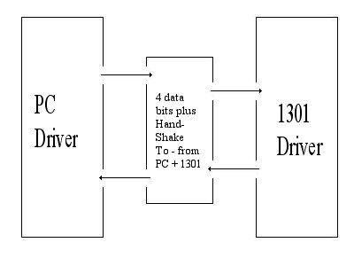
A simple Transfer in interface to prove we could drive the indicators and designed to load data to the 1301 to
save all that data keying. The interface worked and proved the 1301 to PC link was possible.
Rapid data transfer but software needed to transfer in not completed. ( About 126k transfered this way )
Interface Mk1
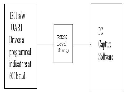
A simple serial interface, the 1301 acts as a software driven UART and drives a Programmed Indicator, the only logic
involved is an RS232 level convertor, output rates of 1200 buad were achieved ! The Image of Initial Orders was captured
from the machine using this interface.
Data rate was slow but over 180k of data got liberated this way.
